Gas that evolves from produced oil and water at an oil production well site can be a major source of emissions.
This blog post covers the most common methods for capturing flash gas from production sites and facilities. We describe five major types of vapor capture techniques, and demonstrate the value of capturing vapors directly from oil and water storage tanks, removing the oxygen and then selling Btu-rich gas. We discuss this topic in more detail in our Wellsite Configurations for Vapor Control webinar.
(Header Image: U.S. GAO, U.S. EPA)
As produced oil, gas, and water are separated and stored, they are kept under progressively lower pressure, allowing lighter hydrocarbons to move from the liquid phase to gas, which accumulates in oil and water storage tanks.
In addition to fugitive emissions from inadequately maintained equipment, vapor can also leak from storage tanks (main image, above) and while loading produced oil into trucks for transportation to downstream facilities.
Although these vapors can be captured, they frequently contain oxygen at levels that cannot be handled by produced gas pipelines. As a result, much of the captured vapor is vented or flared.
Data collected by the Colorado Department of Public Health and the Environment[1] indicates that almost 60% of the emissions of volatile organic compounds (VOCs) and nitrous oxides (NOx) occur after separation.
VOCs and NOX are precursors for ozone formation in the presence of sunlight.
Flaring of tank vapors also generates significant amounts of CO2 which, although not widely regulated, is under increasing scrutiny as part of operators’ ESG commitments.
Operators have several options at their disposal to reduce flaring and greenhouse gas (GHG) emissions. Below we walk through the five different scenarios for operators:
- Flaring, the “do nothing” or status quo option
- Vapor reduction by increasing the generation and capture of vapor prior to storage
- Partial vapor capture using a vapor recovery tower (VRT) and compressor (vapor recovery unit, VRU)
- Full vapor capture using vapor treatment or combustion to mitigate oxygen contamination
- Direct vapor capture from the tanks using a closed-loop emission solution with oxygen removal
Let’s discuss the relative effectiveness of these options.
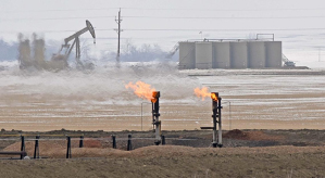
Natural gas flared in April 2018 north of Ross, N.D.. Grand Forks Herald Dec 17,2019
Scenario 1: Flaring (The “Do Nothing” Scenario or Status Quo)
Flaring of tank vapor became a common practice when the U.S. Clean Air Act of 2011 drove the Environmental Protection Agency (EPA) to mandate a 95% reduction in VOC emissions.
Flaring obviously incurs the lowest capital and operating cost, since vapor is simply routed to the flare stack and burned. But it leads to the highest levels of NOx and greenhouse gas emissions.
Economically, losing all that rich vapor (typically > 2,200 BTU/scf) is also not an attractive option. A new site often generates 300,000 scf/d – the energy equivalent of over 100 barrels of oil per day.
However, there are situations where flaring is the only viable alternative, such as a lack of pipeline capacity or unmanageable contaminants in the gas.
Pipeline specifications typically set a limit on contaminants such as oxygen, hydrogen sulfide, and carbon dioxide. For example, oxygen, which is corrosive to pipelines and equipment, is typically limited to 10 parts per million (ppm) or less.
If tank vapor gas contains oxygen higher than pipeline specification, it must be eliminated, typically by flaring, a practice coming under increasing scrutiny by regulators and investors.
Scenario 2: Vapor Reduction
The first approach to reducing flaring and emissions is to reduce the volume of hydrocarbons that convert into vapor in the first place.
The volume of vapor reaching the tank battery can be reduced by raising the oil temperature during the separation process, before it reaches the tanks.
The addition of a heater-treater can help reduce the vapor volume, in addition to performing its traditional function of treating oil-water emulsions.
The addition of a heater-treater can help reduce the vapor volume as well as its traditional function of treating oil-water emulsions.

Example Process Diagram Including Heater-Treater
According to Mesa Applied Technologies, adding a heater-treater can reduce vapor volume by as much as 50%, but the effectiveness depends on the specific oil being treated and the operating temperature of the treater.
This is a relatively low-cost solution but, without adding more equipment downstream of the heater, the balance of the vapor would still be flared.
Depending on the sales line pressure, gas from the treater may also require compression by a vapor recovery unit (VRU) before it can be sold, increasing costs and system complexity.
A “polisher” can be added to take this approach one step further. A polisher is a heated separator operating at low pressure, combining the effects of pressure and temperature to remove even more volatile hydrocarbons and further reduce the produced vapor volume.
The low operating pressure – typically 10 psig or less – usually requires additional pumps to move produced liquids to the tank battery and a VRU to raise the captured gas to sales line pressure, which again increases cost and system complexity.
A polisher can reduce tank vapor volume by as much as 80% and is typically considered for sites with high production rates and significant vapor volumes.
As well as the incremental capital cost, polishers can be tricky to operate and require regular maintenance. They also introduce increased potential for oxygen ingress because of their low operating pressure.
Scenario 3: Partial Vapor Capture
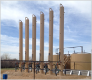
Vapor Recovery Towers, Weld County, Colorado
The most popular method of vapor capture is a Vapor Recovery Tower (VRT).
These tall, cylindrical, low-pressure vessels collect vapor upstream of the storage tanks before it risks becoming contaminated with oxygen.
VRTs usually operate at a pressure of 3-5 psig, with oil staying in the vessel for at least 20 minutes.
Towers treat the oil stream coming from the production separators. Treated oil flows directly from the VRT to storage, while vapor evolved from the oil is compressed with a VRU and commingled with produced gas for sale.
While VRTs are relatively low-cost, they do have some significant drawbacks. Their fixed capacity means they are typically undersized for early production and become oversized as well productivity declines. They are also susceptible to freezing and paraffin blockage in regions prone to cold weather.
Field data from EcoVapor installations indicates that VRTs typically capture between 60% and 80% of the total vapor stream. Inefficient sizing and production stream variations account for some of this range. Additional vapor is generated after the oil is sent to the storage tanks, as well as vapor evolved from produced water, tank loading and unloading, and temperature changes that result in tank “breathing”.
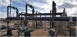
Blower systems feeding a VRU, Permian Delaware Basin
The remaining 20-40% of the vapor is typically flared, contributing to emissions of NOx and VOCs, both precursors of ground-level ozone pollution.
Some operators also install blowers to pull vapor from the tanks and allow the VRU to handle both the VRT and tank vapor streams. While this increases vapor capture, it adds significant cost and increased potential for oxygen contamination.
Scenario 4: Full Vapor Capture
Full vapor capture means recovering vapor from the oil and water tanks and while offloading oil into trucks for transportation.
In above ground oil storage tanks, the very low pressure is close to atmospheric pressure, making tanks vulnerable to air ingress and contamination of the gas by oxygen. This can make it difficult to achieve the typical pipeline specification of <10 ppm O2 (0.001%).
The reward for full vapor capture is additional revenue from the high BTU vapor stream and, more importantly, the associated reduction in flaring and emissions.
Each full vapor capture method captures the vapor stream directly from the tank battery and uses a compressor (VRU) to bring the gas up to sales line pressure.
Blower. The most basic configuration uses a blower to pull vapor from the tanks and match the VRU suction pressure. This method is low cost and the least complex solution, but it does nothing to address oxygen contamination which can prevent sale of the recovered gas.
Gas Blanket. Gas blankets maintain a higher pressure in the storage tanks by introducing a controlled amount of produced gas into the tank battery. This creates a positive pressure difference between the tank and the atmosphere outside, discouraging air ingress.
Gas blanketing is widely used but operators report mixed results – especially where the pipeline oxygen specification is very low. Nevertheless, if there is sufficient produced gas at the site, commingling the blanketed tank gas with produced gas can be an effective way of selling the entire vapor stream.
Operational complexity can also be a drawback of gas blankets. The effectiveness of gas blankets controlled by a regulator varies widely, because of pressure variations within the battery, limited (if any) tank pressure measurements and the regulator’s slow response time.
Newer gas blanketing designs use programmable logic and pressure sensors that communicate with solenoid control valves. These are reported to be more effective, but are more complex and typically require greater hands-on attention.
Both designs are vulnerable to increased venting during a production surge or sudden pressure spike because they operate close to the maximum working pressure of the tanks, which makes it difficult to optimize operations and production cycles.

Scenario 5: Direct Vapor Capture From The Tanks (Oxygen Removal) – Closed-Loop Emissions Solution
Oxygen Removal. The most reliable and cost-effective full capture method is to remove oxygen from the vapor stream to ensure all the captured vapor can be sold into the pipeline, regardless of its origination.
EcoVapor’s ZerO2 solution uses a catalytic reactor to convert oxygen into carbon dioxide and water and can treat vapor streams containing up to 50,000 ppm O2. The ZerO2 solution enables operators to capture the full vapor stream without any additional equipment (other than the VRU).
Operators using the ZerO2 report that it is an effective and easy-to-operate solution that reduces emissions while maximizing revenue and virtually eliminating unplanned flaring.
The ZerO2 solution typically generates the highest ROI of all vapor mitigation options because it allows the entire vapor stream to be sold instead of flared, lost to fugitive emissions or venting.
Importantly, ZerO2 units have no moving parts and typically deliver available uptime of 99%+.
Is an Emergency Flare Required?
To avoid shutting in production when equipment trips or requires maintenance, conventional wisdom says that a flare will always be required wherever there is a tank battery.
This is especially true with older or poorly sized vapor compression equipment that results in regular performance upsets and increased maintenance.
In many states, flares are mandated for safety reasons.
Industry’s long-term goal is to eliminate the practice of routine flaring to improve environmental performance and boost economic returns. The ZerO2 solution checks all the boxes when it comes to achieving these twin objectives.
Side-by-Side Comparison
The table below compares key attributes of the methods we’ve discussed.
Remember that, in many cases, a combination of these vapor control methods can be used to achieve the best fits with your objectives and operating situation.
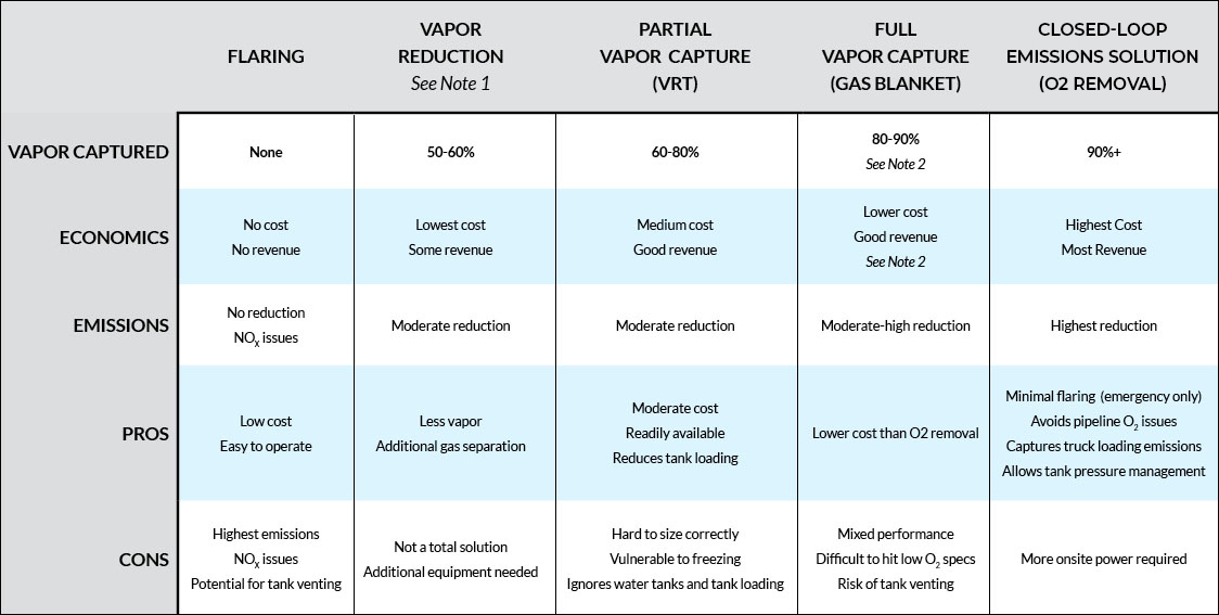
(CLICK TO ENLARGE)
Notes:
- For configurations using a VRU, recovery is typically limited by VRU uptime
- Revenue and emissions reduction at risk if O2 contamination prevents sale of recovered gas
About EcoVapor
EcoVapor Recovery Systems provides solutions to pressing oil and natural gas production problems. EcoVapor’s technical team has extensive expertise in vapor recovery processes, and includes world-class engineers with an innovative approach to industry challenges. In over 120 installations in all major US basins, our patented ZerO2 solution helps oil and gas producers meet their air emissions and regulatory compliance goals. EcoVapor is headquartered in Denver, Colorado and has field locations in Greeley, Colorado and Midland, Texas.
Contact
EcoVapor Recovery Systems
700 17th St., Suite 950
Denver, CO 80202
Email: Info@EcoVaporRS.com
Phone: 844-NOFLARE (844-663-5273)